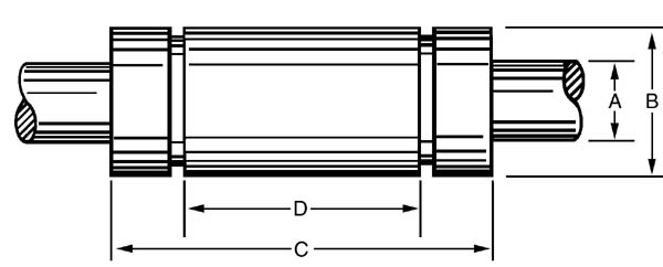
Specifications
| Bearing No. |
Working Bore |
Outside Diameter |
Length |
| A |
LR |
LRP |
| Tolerance +0000 to |
Tolerance +0000 to |
Concentricity (T.I.R.) |
B |
Tolerance +0000 to |
C |
Tolerance +0000 to |
| 6 |
0.3750 |
-0.0005 |
-0.0003 |
0.0005 |
0.6250 |
-0.0004 |
0.875 |
-0.015 |
| 8 |
0.5000 |
-0.0005 |
-0.0003 |
0.0005 |
0.8750 |
-0.0004 |
1.250 |
-0.015 |
| 10 |
0.6250 |
-0.0005 |
-0.0003 |
0.0005 |
1.1250 |
-0.0004 |
1.500 |
-0.015 |
| 12 |
0.7500 |
-0.0005 |
-0.0003 |
0.0005 |
1.2500 |
-0.0004 |
1.625 |
-0.015 |
| 16 |
1.0000 |
-0.0005 |
-0.0003 |
0.0005 |
1.5625 |
-0.0004 |
2.250 |
-0.015 |
| 20 |
1.2500 |
-0.0006 |
-0.0004 |
0.0010 |
2.0000 |
-0.0005 |
2.625 |
-0.020 |
| 24 |
1.5000 |
-0.0006 |
-0.0004 |
0.0010 |
2.3750 |
-0.0005 |
3.000 |
-0.020 |
| 32 |
2.0000 |
-0.0008 |
-0.0005 |
0.0015 |
3.0000 |
-0.0006 |
4.000 |
-0.020 |
| 40 |
2.5000 |
-0.0010 |
-0.0005 |
0.0015 |
3.7500 |
-0.0008 |
5.000 |
-0.025 |
| 48 |
3.0000 |
-0.0012 |
-0.0006 |
0.0015 |
4.5000 |
-0.0010 |
6.000 |
-0.030 |
| 64 |
4.0000 |
-0.0020 |
-0.0010 |
0.0020 |
6.0000 |
-0.0012 |
8.000 |
-0.040 |
| Bearing
No. |
Distance between
retaining rings |
Retaining Ring Groove
Dimensions |
Maximum Shaft Diameter |
Ball Diameter |
No. of Ball Circuits |
Bearing Weight (lbs) |
| D |
Tolerance |
Groove Width |
Groove Diameter |
LR |
LRP |
| 6 |
0.562 |
� 0.010 |
0.039 |
0.593 |
0.3745 |
0.3747 |
1/16 |
6 |
0.05 |
| 8 |
0.875 |
� 0.010 |
0.046 |
0.770 |
0.4995 |
0.4997 |
5/64 |
7 |
0.07 |
| 10 |
1.000 |
� 0.010 |
0.056 |
1.057 |
0.6245 |
0.6247 |
3/32 |
7 |
0.15 |
| 12 |
1.062 |
� 0.010 |
0.056 |
1.178 |
0.7495 |
0.7497 |
3/32 |
8 |
0.22 |
| 16 |
1.625 |
� 0.010 |
0.068 |
1.500 |
0.9995 |
0.9997 |
1/8 |
8 |
0.45 |
| 20 |
1.875 |
� 0.010 |
0.068 |
1.886 |
1.2494 |
1.2496 |
5/32 |
9 |
0.93 |
| 24 |
2.250 |
� 0.015 |
0.086 |
2.255 |
1.4994 |
1.4996 |
5/32 |
9 |
1.45 |
| 32 |
3.000 |
� 0.015 |
0.103 |
2.880 |
1.9992 |
1.9996 |
7/32 |
9 |
2.85 |
| 40 |
3.750 |
� 0.015 |
0.120 |
3.562 |
2.4990 |
2.4995 |
9/32 |
9 |
5.95 |
| 48 |
4.500 |
� 0.015 |
0.120 |
4.310 |
2.9988 |
2.9994 |
5/16 |
9 |
10.00 |
| 64 |
6.000 |
� 0.020 |
0.139 |
5.745 |
3.9980 |
3.9990 |
7/16 |
9 |
23.20 |
Notes:
- The groove widths marked match standard retaining ring thicknesses.
- To order wipers - one end, add the suffix W, i.e. LR-W
- To order wipers - both ends, add the suffix WW, i.e. LR-WW
- For shaft to bearing selection a clearance of 0.0005 is recommended.
- Shaft diameters greater than specified could cause ball loss during
insertion.
| Bearing
No. |
Shaft Dia. |
Revolutions
per minute |
| Linear Only |
50 |
100 |
200 |
300 |
500 |
900 |
1200 |
1500 |
1800 |
2400 |
3650 |
| LR-6 |
0.3750 |
70 |
61 |
48 |
39 |
33 |
29 |
23 |
21 |
20 |
18 |
17 |
15 |
| LR-8 |
0.5000 |
185 |
161 |
128 |
102 |
89 |
76 |
61 |
56 |
52 |
48 |
44 |
39 |
| LR-10 |
0.6250 |
283 |
246 |
195 |
156 |
136 |
116 |
93 |
85 |
79 |
74 |
68 |
59 |
| LR-12 |
0.7500 |
325 |
283 |
224 |
179 |
156 |
133 |
107 |
98 |
91 |
85 |
78 |
68 |
| LR-16 |
1.0000 |
450 |
392 |
311 |
248 |
216 |
185 |
149 |
135 |
126 |
117 |
108 |
95 |
| LR-20 |
1.2500 |
600 |
522 |
414 |
330 |
288 |
246 |
198 |
180 |
168 |
156 |
144 |
126 |
| LR-24 |
1.5000 |
935 |
813 |
645 |
514 |
449 |
383 |
309 |
281 |
262 |
243 |
224 |
196 |
| LR-32 |
2.0000 |
1340 |
1166 |
925 |
737 |
643 |
549 |
442 |
402 |
375 |
348 |
322 |
281 |
| LR-40 |
2.5000 |
1830 |
1592 |
1263 |
1018 |
878 |
750 |
604 |
549 |
512 |
475 |
439 |
-- |
| LR-48 |
3.0000 |
2370 |
2062 |
1635 |
1304 |
1138 |
972 |
782 |
711 |
663 |
616 |
-- |
-- |
| LR-64 |
4.0000 |
5285 |
4598 |
3647 |
2907 |
2537 |
2167 |
1744 |
1585 |
1480 |
-- |
-- |
-- |
Notes:
- Load ratings based on use with hardened shaft - Rockwell 60C.
- Based on travel life of 10 million inches.
- For speeds and loads not listed, consult Linear Rotary Bearings.
Standard AISI C-1060 Steel hardened to Rockwell 58/63C or 440C.
Stainless steel shafts hardened to Rockwell 50/55C are charted
below. Shafting can be supplied up to 12 feet long or can be cut to
any length. Special tolerances, dimensions or end matching will be
promptly quoted.
All units in inches, except where noted.
| Nominal Diameter* |
Tolerance Code |
Tolerances |
Weight per inch (lb) |
Min. Depth of Hardness |
| 3/8 |
A |
0.3735 / 0.3740 |
0.031 |
0.040 |
| B |
0.3740 / 0.3745 |
| 1/2 |
A |
0.4985 / 0.4990 |
0.055 |
0.060 |
| B |
0.4990 / 0.4995 |
| R |
0.4998 / 0.5000 |
| 5/8 |
A |
0.6235 / 0.6240 |
0.086 |
0.060 |
| B |
0.6240 / 0.6245 |
| R |
0.6248 / 0.6250 |
| 3/4 |
A |
0.7485 / 0.7490 |
0.125 |
0.060 |
| B |
0.7490 / 0.7495 |
| R |
0.7498 / 0.7500 |
| 1 |
A |
0.9985 / 0.9990 |
0.222 |
0.080 |
| B |
0.9990 / 0.9995 |
| R |
0.9998 / 1.0000 |
| 1 1/4 |
A |
1.2485 / 1.2490 |
0.348 |
0.080 |
| B |
1.2490 / 1.2495 |
| R |
1.2498 / 1.2500 |
| 1 1/2 |
A |
1.4984 / 1.4969 |
0.500 |
0.080 |
| B |
1.4989 / 1.4994 |
| R |
1.9997 / 2.0000 |
| 2 |
A |
1.9980 / 1.9987 |
1.391 |
0.100 |
| B |
1.9987 / 1.9994 |
| R |
1.9997 / 2.0000 |
| 2 1/2 |
A |
2.4977 / 2.9983 |
1.391 |
0.100 |
| B |
2.4985 / 2.4993 |
| R |
2.4995 / 2.5000 |
| 3 |
A |
2.9974 / 2.9983 |
2.003 |
0.100 |
| B |
2.9983 / 2.9992 |
| R |
2.9994 / 3.0000 |
| 4 |
A |
3.9964 / 3.9976 |
3.560 |
0.100 |
| B |
3.9976 / 3.9988 |
| R |
3.9991 / 4.0000 |
*For other sizes and tolerance, consult Linear Rotary Bearings.
- Chart
3 - Load Correction Factor (Kl) vs. Travel Life in Millions of
Inches
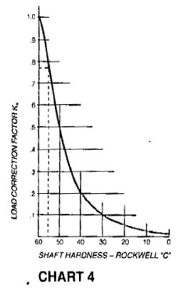
- Chart
4 - Load Correction Factor (Kh) vs. Shaft Hardness - Rockwell
"C"
A pick and balance machine requires two linear rotary bearings.
Total load is 800 lbs. Maximum rotation is 300 RPM. Shafts are
to be hardened to Rc 55C. Travel life is required to be 25,000,000
inches.
Calculations:
Load bearing = 800 lbs / 2 = 400 lbs. @ 300 RPM
Shaft hardness RC 55: from Chart
4 we obtain a load correction factor Kh = 0.76
Load factor for 25,000,000 inches: from Chart
3 we obtain Kl = 0.75
Factored load capacity = 400 / (Kh * Kl) = 400 / (0.76 * 0.75) = 702
lbs.
From Chart
1, we obtain for 702 lbs. @ 300 RPM a Linear Rotary bearing rated at
878 lbs. (LR-40)
Calculate margin of safety = (878 / 702) - 1 = 25%
NOTE: Means of measuring inches of travel = Shaft diameter (inches) x
3.1416 x Revolutions + Linear Inches Travel
Because of its inherent geometric configuration, the linear rotary
bearing has no inner race. Therefore, to take full advantage of its
superior characteristics, proper shaft selection is mandatory. Under
"Design
Guidelines" correct diameters were suggested. To achieve
the full rated life cycle and smooth operation, the shaft shoud be AISI
C-1000 steel case hardened to Rockwell 58-63C or from 440 Stainless Steel,
case hardened to Rockwell 50-55C. If shaft hardness cannot be met,
see Chart 4
for the reduction factor.
The lubrication factor is a function of speed, linear plus rotary,
where applicable. The faster the ball movement, the less viscous the
oil required. It is theoretically possible to use no lubricant at
high speeds. The load factor must also be considered. It is
suggested that a light machine oil be used, if only to prevent corrosion.
|